Horizon's Refit
Updated November 2005.
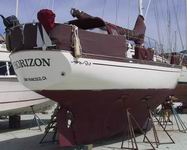 Boat refits tend to be ongoing and Horizon's refit will be no
exception. The haulout phase of this refit really got going in February 2003
when we realized there was enough money saved to put the new engine into
Horizon. We had purchased the Yanmar at the Miami boat show in 2002
but for 9 months it sat in our shed at the marina while we saved more money.
Like most things nautical, my original estimate to haul and install the
engine was far too low, but then we had lots of unexpected surprises. In the
end, our "2 week haul" turned into 10 weeks and the cost ballooned to 3 times
our worst-case estimate, but we think the results are worth it.
Boat refits tend to be ongoing and Horizon's refit will be no
exception. The haulout phase of this refit really got going in February 2003
when we realized there was enough money saved to put the new engine into
Horizon. We had purchased the Yanmar at the Miami boat show in 2002
but for 9 months it sat in our shed at the marina while we saved more money.
Like most things nautical, my original estimate to haul and install the
engine was far too low, but then we had lots of unexpected surprises. In the
end, our "2 week haul" turned into 10 weeks and the cost ballooned to 3 times
our worst-case estimate, but we think the results are worth it.
Batteries - The first major change was replacing our two aging
Prevailer 4D batteries with four 6 volt
Concorde Lifeline
AGM batteries. We never liked the original battery location on a shelf above
and behind the engine; it was too hot and the weight was too high and too far
aft. The perfect place would be in the center of the boat, amid-ships in the
shallow bilge area between the water and diesel tanks - but the only access
to that area was a small inspection hatch in the cabin sole. In thinking
over the problem, it became obvious that 6 volt batteries could fit through
the hatch and enough room could be made for 4 of them. A change to 6 volt
batteries raised another consideration: two batteries would be wired in
series to make 12 volts then the two pairs would be in parallel when the
battery switch was set to BOTH. Because of this it was extremely important
that all batteries be matched and have the same characteristics. We trooped
off to Boat US to order the 6 volt Prevailer batteries listed in their
catalog and specified they all be the same lot number. Seven months and
several false starts later Boat US returned our money and informed us they
could not deliver same-lot Prevailer batteries. About that time AGM batteries
were coming into vogue. The specs for the Concorde batteries looked great and
the manufacturer told us they could ship same lot numbers. Off we went to
Boat US again and 2 weeks later we had the batteries. We do not have enough
experience with them yet to give much of a long-term recommendation but so
far we are pleased. You can just see them at the top of the picture in the
diesel tank section.
As long as we were rewiring everything, we added 250 Amp fuses to each
battery and a 450 Amp shunt for a new
CruzPro
VAH110 battery monitor. Before we went cruising, I had designed and built our
previous battery monitor/alarm system. But a lightning strike in 1999 fried
that box and as one critical part is no longer available, it is not
rebuildable. After much searching we decided to replace it with the VAH110.
That unit monitors battery voltage and current usage, has a large, easy to
read display and has adjustable alarms for most everything battery related.
Windlass - We finally got our new, but 5 year old, H2F model
Ideal Windlass
mounted and wired. We picked that brand because it is all stainless steel and
bronze and has a decent single-action manual backup system. We did have some
initial problems that we hope will not be too difficult to cure. The first
problem we found was our 3/8" HT chain jumps the wildcat even under light
(less than 50 lb) load. We have also not been able to stop the gear box from
weeping gear lube through the front cover gasket. It turns out the wildcat we
got with the windlass 5 years ago is an older model and they had lots of
problems with that. When we have a bit more money saved up, we will order a
new wildcat and some spare gaskets.
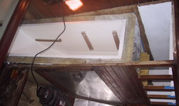
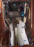
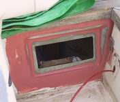
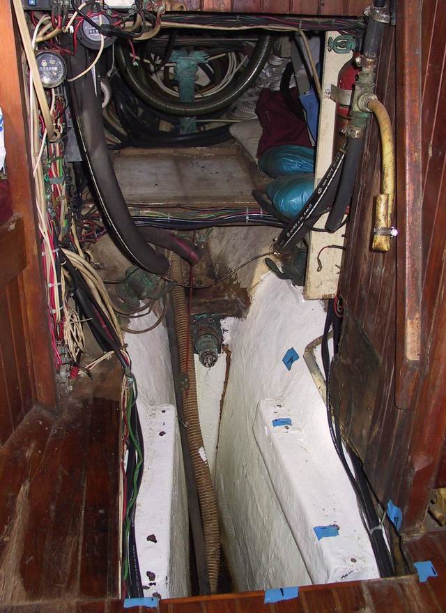
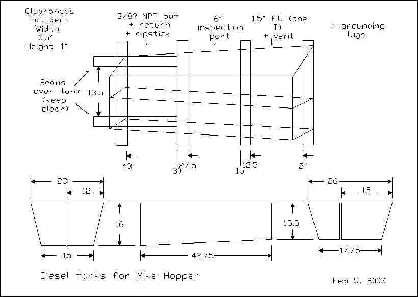
 Diesel tanks - When the original black iron fuel tank started to
leak it had to be cut out in pieces. Horizon was built around her tankage
and the only access into that area was down between the cabin sole stringers
or from the engine area astern. The curve of the hull did not allow a single
new tank to go back into the original space so two new aluminum
tanks
were made by
C L Mattson,
tapered such that they could be slid into place from astern. We opted to
seal the aluminum by having them powder coated by
ProCoat. The old engine
was out anyway so after the area was lined with vertical neoprene strips, the
tanks were slid into place then blocked and foamed. A plywood end-cap
fiberglassed across the aft end of the tanks gives a mounting surface for the
sea water strainer and water maker filter and has a stainless steel backing
plate to protect the tanks from errant drills and screws. Of course, replacing
one fuel tank with two meant an increase in plumbing complexity to allow
separate fill and draw/return.
Diesel tanks - When the original black iron fuel tank started to
leak it had to be cut out in pieces. Horizon was built around her tankage
and the only access into that area was down between the cabin sole stringers
or from the engine area astern. The curve of the hull did not allow a single
new tank to go back into the original space so two new aluminum
tanks
were made by
C L Mattson,
tapered such that they could be slid into place from astern. We opted to
seal the aluminum by having them powder coated by
ProCoat. The old engine
was out anyway so after the area was lined with vertical neoprene strips, the
tanks were slid into place then blocked and foamed. A plywood end-cap
fiberglassed across the aft end of the tanks gives a mounting surface for the
sea water strainer and water maker filter and has a stainless steel backing
plate to protect the tanks from errant drills and screws. Of course, replacing
one fuel tank with two meant an increase in plumbing complexity to allow
separate fill and draw/return.
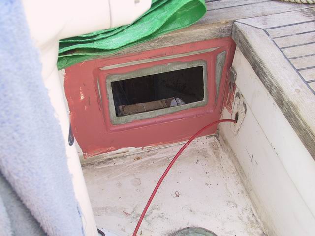
Plumbing - When we hauled we found that the engine intake seacock
needed to be replaced so this gave us an opportunity to correct a long
standing nuisance. Horizon's head had always tended to recirculate if
vigorously pumped for too long, plus having 4 seacocks in the head area made
me nervous. The cure for a sister ship was to move the head intake to the
other side of the hull. We found an easier method; we increased the size of
the new main water intake to 1 1/4" with matching sea water strainer, then a
manifold feeds the engine, water maker, galley salt water foot pump and head
intake. Changing fittings to let the shower sump pump share a seacock with
the head basin reduced the number of seacocks in the head area to two, a far
more comfortable number. We ended up replacing virtually every hose on
Horizon. Luckily we found a local
Amazon Hose
store, the great folks who seem to stock every USCG approved hose and fitting
and clamp at prices half what the chandleries want.
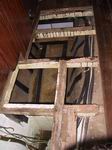
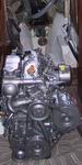
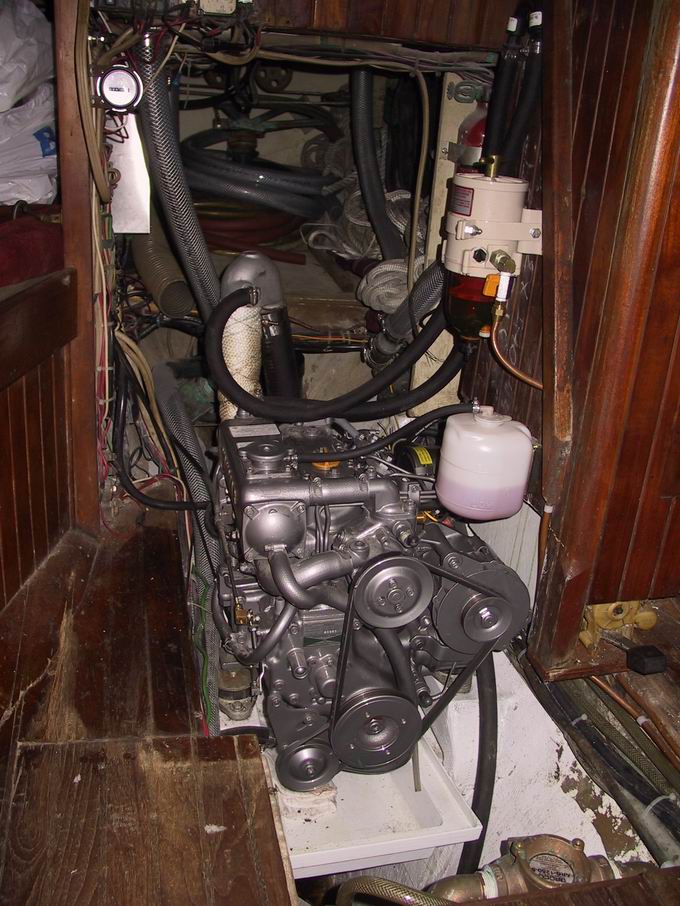
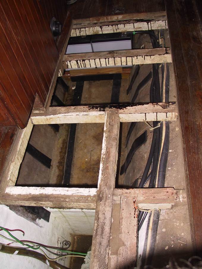
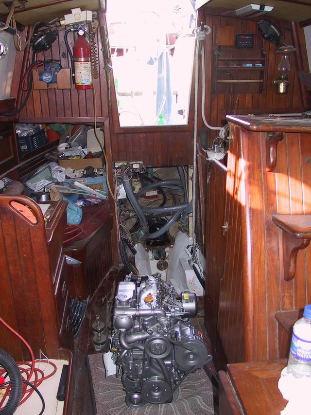
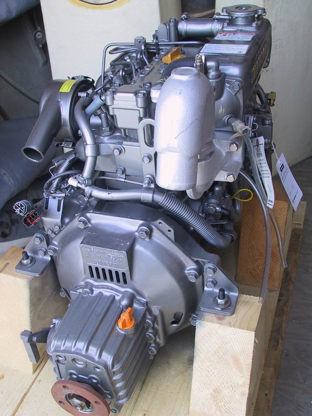
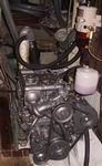 Engine - Horizon's original engine was an old and reliable but
25 year old
Volvo MD-11C
which we wanted to replace with a new
Yanmar 3GM30F
with the 3P gear box. But how to squeeze a short fat Yanmar into the space
occupied by the tall thin Volvo? As the pictures show, the old timbers
angled in toward the stern and quickly narrowed too much for the Yanmar to
fit. The front mounts were not a problem, there was ample height and width
for those, and the engine would just fit between the hull for it's entire
length, but there was not nearly enough room for the rear mounts in their
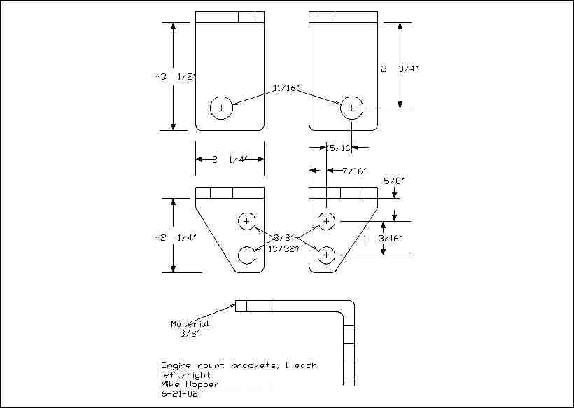
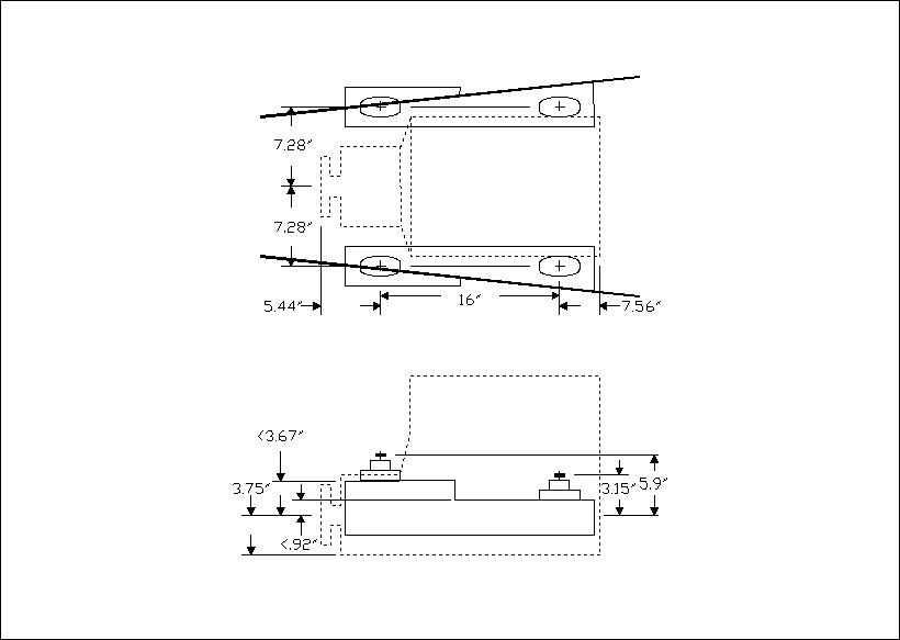
factory stock location. We decided to replace the stock mounts with new
short
R&D
engine mounts and have new rear
brackets
fabricated that would
raise
the rear mounts high enough on the flare to fit between the hull sides.
Vince of Composite Marine fiberglassed the stepped engine beds and also
fabricated a removable engine drip pan.
Engine - Horizon's original engine was an old and reliable but
25 year old
Volvo MD-11C
which we wanted to replace with a new
Yanmar 3GM30F
with the 3P gear box. But how to squeeze a short fat Yanmar into the space
occupied by the tall thin Volvo? As the pictures show, the old timbers
angled in toward the stern and quickly narrowed too much for the Yanmar to
fit. The front mounts were not a problem, there was ample height and width
for those, and the engine would just fit between the hull for it's entire
length, but there was not nearly enough room for the rear mounts in their
factory stock location. We decided to replace the stock mounts with new
short
R&D
engine mounts and have new rear
brackets
fabricated that would
raise
the rear mounts high enough on the flare to fit between the hull sides.
Vince of Composite Marine fiberglassed the stepped engine beds and also
fabricated a removable engine drip pan.
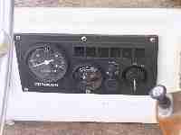
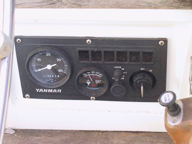
Other things we needed for the new engine were prop shaft and propeller and
new 2" exhaust system throughout. As long as we were about it, we added a
PSS
dripless shaft seal and a new Racor fuel filter. We also added a water temp
gauge to the engine panel, moving the original buzzer behind the panel. The
new engine purrs (clatters?) right along but not without some initial startup
problems...
Hint: It is advisable to open the exhaust gate valve at the hull
before starting an engine for the first time. This avoids a rather impressive
KA-POW when the weakest exhaust fitting explodes, raising the shelf
above the muffler a good inch and raising everyone's blood pressure several
points.
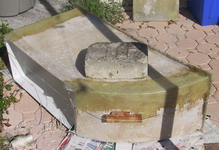
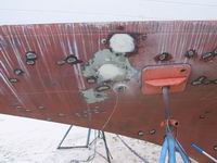
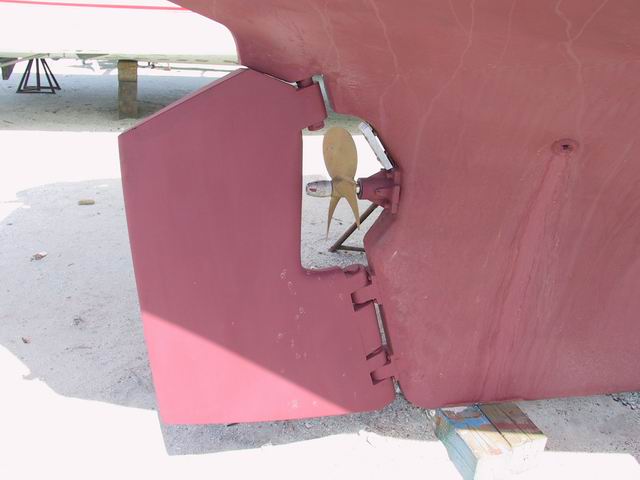
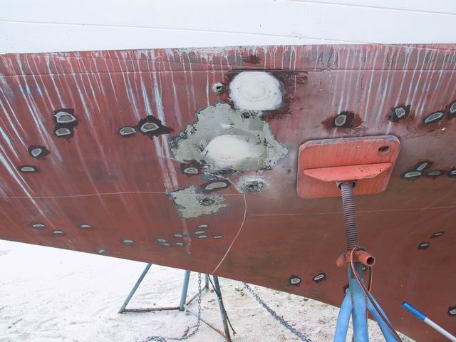
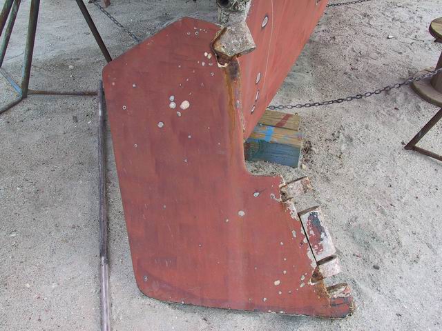
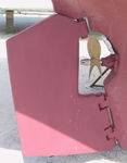 Rudder and the pox - When we hauled we found more hull blisters than
expected and the rudder showed significant problems around the pintles. Rust
from the rudder fittings and fasteners was pushing the fiberglass away from
the body. It was time to have the rudder rebuilt and Vince of Composite
Marine was given that job. Of course, before Vince could start fiberglassing
a new rudder, we had to find someone in the greater Tampa Bay area who could
fabricate new fittings from 2 inch thick stainless steel stock. That alone
took 3 weeks and did not come cheap. Sigh.
Rudder and the pox - When we hauled we found more hull blisters than
expected and the rudder showed significant problems around the pintles. Rust
from the rudder fittings and fasteners was pushing the fiberglass away from
the body. It was time to have the rudder rebuilt and Vince of Composite
Marine was given that job. Of course, before Vince could start fiberglassing
a new rudder, we had to find someone in the greater Tampa Bay area who could
fabricate new fittings from 2 inch thick stainless steel stock. That alone
took 3 weeks and did not come cheap. Sigh.
While the new rudder was being built, Lisa, my mate, was doing a
thoroughly excellent job of fixing the blisters through grinding, fairing,
and barrier coating.
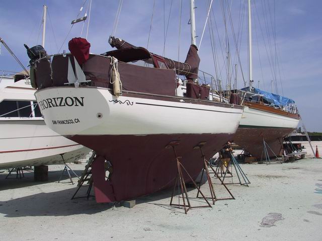
Everything took much longer than expected but the final results are worth it.
Her bottom is fair and solid, the rudder is once again bullet-proof, all is
right with Horizon's hull, and she once again has an engine that
starts immediately. I credit the dripless shaft seal, but for the first time
in her life, even her bilge is dry. I hope that desn't mean something new is
about to break...
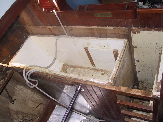
 Horizon gets a new fridge - Part I: Insulation -
Horizon has always had a problem with her ice box. In the tropics the Adler
Barbour Cold Machine compressor would run almost 50% of the time which
was a real power user, and the teak bulkhead behind the adjacent settee
cushion would sweat. The box was originally designed for block ice and had a
5" deep water sump with drain tube under teak grates. While we liked the
grates, the drain sump was too deep to reach from the top of the box and so,
was unusable.
Horizon gets a new fridge - Part I: Insulation -
Horizon has always had a problem with her ice box. In the tropics the Adler
Barbour Cold Machine compressor would run almost 50% of the time which
was a real power user, and the teak bulkhead behind the adjacent settee
cushion would sweat. The box was originally designed for block ice and had a
5" deep water sump with drain tube under teak grates. While we liked the
grates, the drain sump was too deep to reach from the top of the box and so,
was unusable.
A few years ago we made a first attempt to better insulate the box by sealing
the drain and adding a false floor just under the grates. We then drilled
about 20 holes through the box interior sides and bottom and pumped in
two-part closed cell foam to fill all the cavities. But it was to no avail;
there was little change in compressor running time and the teak still
sweated.
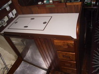
 In November 2004 we decided to cure the problem once and for all and totally
rebuild the box. The first step was to enlist the help of cabinetry
craftsman Brian Fitz who cut out the counter top over the box. Once exposed, we
found the box had originally been built as an interior fiberglass shell
covered with 1 inch of foam then a second fiberglass shell; the two shells
glassed together at the top to form a single unit sandwich. Around that,
another inch or so of what looked to be scrap Airex hull core panels were
randomly fitted between the ice box unit and the surrounding area. Most of
the foam panels were sopping wet from decades of condensation and leaks.
In November 2004 we decided to cure the problem once and for all and totally
rebuild the box. The first step was to enlist the help of cabinetry
craftsman Brian Fitz who cut out the counter top over the box. Once exposed, we
found the box had originally been built as an interior fiberglass shell
covered with 1 inch of foam then a second fiberglass shell; the two shells
glassed together at the top to form a single unit sandwich. Around that,
another inch or so of what looked to be scrap Airex hull core panels were
randomly fitted between the ice box unit and the surrounding area. Most of
the foam panels were sopping wet from decades of condensation and leaks.
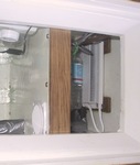
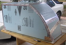
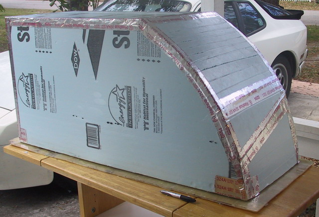
We decided to insulate the new box with 2" of Styrofoam panels covered by 1"
of a NASA-developed heat shield product available from
Fourwinds Enterprises.
Claims were that combination of insulation was tested to be the equivalent of
7" of foam alone. In addition to the 3" total insulation depth on each side,
we wanted a 1/2" air space on the side against the settee bulkhead to
eliminate the sweating issue.
 Measuring the box showed that it needed to be narrowed by 2". Cutting the
bottom off horizontal about 2" lower than the original grate location and
doing away with the grates would regain some useable volume lost by narrowing
the box.
Measuring the box showed that it needed to be narrowed by 2". Cutting the
bottom off horizontal about 2" lower than the original grate location and
doing away with the grates would regain some useable volume lost by narrowing
the box.
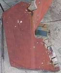
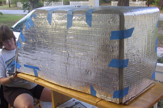
With those requirements in mind Lisa started cutting and reshaping the
original inner fiberglass shell to the new dimensions. When fiberglassing
the pieces back together, she added "ears" all around the top. The ears are
3" wide on the sides as a sealing flange for the insulation, and 4" wide on
the ends to also connect to new cross supports. She coated the interior of
the box with a thick layer of gel coat to give a smooth, slick, easy to clean
surface. She used Liquid Nails to attach the layers of Styrofoam panels to
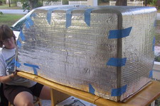
the fiberglass and sealed each seam with aluminum tape. The heatshield was
encased in vapor barrier material then slid over the Styrofoam and sealed to
the top flanges with liberal amounts of 5200. We hope never to have to worry
about soggy insulation again!
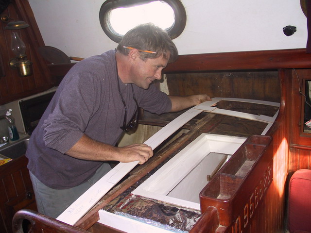
 The rework was complete on January 19, 2005 so we took a deep breath and slid
the fridge box unit with insulation into the cabinetry. On the settee side
we added a thin fiberglass panel and spaced that off the bulkhead with 3/8"
thick PVC slats to give the air gap we wanted. Everything fit (almost)
exactly as expected. The space we left for the tank vent copper tubing on
the hull end was not quite deep enough so the box ended up sitting about 1/4"
farther inboard than expected. Near enough! We left the cabinetry
reconstruction to Brian.
The rework was complete on January 19, 2005 so we took a deep breath and slid
the fridge box unit with insulation into the cabinetry. On the settee side
we added a thin fiberglass panel and spaced that off the bulkhead with 3/8"
thick PVC slats to give the air gap we wanted. Everything fit (almost)
exactly as expected. The space we left for the tank vent copper tubing on
the hull end was not quite deep enough so the box ended up sitting about 1/4"
farther inboard than expected. Near enough! We left the cabinetry
reconstruction to Brian.
About a month later the work was complete. Brian did an excellent job with
the new counter top and the box hatch lids now sport teak trim, flush top
hinges and an extra sealing rim to reduce heat losses from the top. For the
finishing touches, Lisa varnished all the box cabinetry with 3 appropriately
thinned coats of
Epifanes
Clear Gloss Varnish followed by 3 coats of Rubbed Effect Varnish. The results
were well worth the effort.
Horizon gets a new fridge - Part II: Refrigeration - We
had heard of a new marine refrigeration process involving a Sterling pump and
using carbon-dioxide as the eco-friendly refrigerant medium and ran across
AvXcel's
TropiKool
web site. At the February 2005 Miami Boat Show we spent about an hour with the
engineer talking about the system. He explained how the TropiKool
refrigeration process worked, how the unit had reduced power requirements
over other systems, and showed us very convincing test results. In a
nutshell, the Sterling compressor is a variable displacement linear pump with
only one moving part and that part rides on a helium gas bearing. With no
contact friction, longevity should be impressively good and mechanical losses
minimal. Charging the system requires no fancy gauges or exotic consumables,
only a thermometer and CO2 cartridges which can be found cheaply anywhere in
the world.
We walked away from that discussion ready to sign up as beta testers for the
TropiKool-40 and trooped over to the booth of
HotWire Enterprises,
our local TropiKool distributor and ex-marina mates, to do just that.
There are two caveats to using the TropiKool system: mounting and
noise/vibration. The system relies on thermosiphon effects so the compressor
must be mounted higher than the evaporator and the refrigerant lines must be
short and continuously slope downwards from the pump to the evaporator. That
precludes the standard practice of mounting the compressor in a lazarette and
running long refrigerant lines up and over around and through as we do with
pressure driven compressors.
Secondly, the compressor with it's cooling fan runs continuously with the
displacement (capacity) of the pump varying with load. The thermosiphon
criteria means the compressor must be mounted inside the cabin near the
refrigerator so operating noise and vibration become issues.
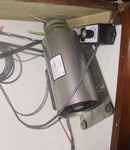
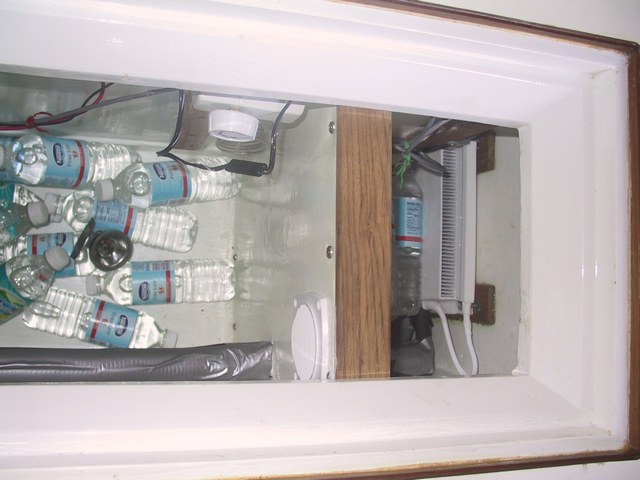
The best place for us to mount the compressor is the cavity behind the stove
on the athwart bulkhead next to the hull end of the refrigerator. The
evaporator will be in a newly build freezer section on the opposite end of
the refrigerator. This configuration meets the mounting and coolant line
requirements. We will try mounting the compressor on box frame suspended
neoprene which should dampen much of the vibration. An existing slide-up
cover panel between the stove and the hull will help reduce the noise factor.
 Horizon gets a new fridge - Part III: TropiKool Installation - We
received our TropiKool unit from Hotwire in early July and started the
install. We constructed a freezer divider with 1.5" of blue foam board
skinned with thin fiberglass panels. An Adler Barbour C7210 spill-over fan
w/thermostat mounted in the divider draws cold air from the freezer to cool
the refrigerator. That configuration gives us two temperature controls: the
one for the TropiKool controls the freezer and the spill-over fan controls
the refrigerator. Placement of the freezer divider gives us a 1.1
ft3 freezer and a 3.8 ft3 refrigerator section. We
ended up mounting the compressor to the bulkhead using grommets in the base
plate mounting holes with additional soft grommets either side which isolates
the base plate from the mounting screws and the bulkhead. The evaporator is
screwed to teak slats epoxied to the inside of the box using vibration
isolators supplied with the unit. Both the evaporator and freezer divider are
attached to epoxied mounts to avoid having screw penetrations that would act
as heat pipes and be a source of condensation outside the box.
Horizon gets a new fridge - Part III: TropiKool Installation - We
received our TropiKool unit from Hotwire in early July and started the
install. We constructed a freezer divider with 1.5" of blue foam board
skinned with thin fiberglass panels. An Adler Barbour C7210 spill-over fan
w/thermostat mounted in the divider draws cold air from the freezer to cool
the refrigerator. That configuration gives us two temperature controls: the
one for the TropiKool controls the freezer and the spill-over fan controls
the refrigerator. Placement of the freezer divider gives us a 1.1
ft3 freezer and a 3.8 ft3 refrigerator section. We
ended up mounting the compressor to the bulkhead using grommets in the base
plate mounting holes with additional soft grommets either side which isolates
the base plate from the mounting screws and the bulkhead. The evaporator is
screwed to teak slats epoxied to the inside of the box using vibration
isolators supplied with the unit. Both the evaporator and freezer divider are
attached to epoxied mounts to avoid having screw penetrations that would act
as heat pipes and be a source of condensation outside the box.
When we first tried to install the TropiKool unit we ran into some problems.
The first was that the CO2 fill port comes soldered in the tubing
9" from the condenser cap which would be impossible to reach with our top
loading box configuration
(drawing)
. We added a 12" section of tubing between the
condenser cap and the fill port to get around that problem. When we charged
the system the first time we found that while the unit did cool, it
did not cool enough to maintain freezing temperatures. Since the unit was
always running full bore, the buzzing of the compressor was objectionable.
We tried a few things but were distracted with other projects over the
summer.
 At the November 2005 St. Petersburg Sail America boat show, we spent some
time with Tom Henderson, the developer of the TropiKool system. He visited
Horizon and suggested the problem might be where the tubing entered
the refrigerator box through a 4" long 2" diameter hole. There was not
enough drop to the tubing which reduced the amount of liquid CO2
that could make it to the evaporator. He left us with a new control
electronics unit with a low-voltage cutoff feature our early unit did not
have and a new 2-part condenser cap that will make future compressor work
much more manageable.
At the November 2005 St. Petersburg Sail America boat show, we spent some
time with Tom Henderson, the developer of the TropiKool system. He visited
Horizon and suggested the problem might be where the tubing entered
the refrigerator box through a 4" long 2" diameter hole. There was not
enough drop to the tubing which reduced the amount of liquid CO2
that could make it to the evaporator. He left us with a new control
electronics unit with a low-voltage cutoff feature our early unit did not
have and a new 2-part condenser cap that will make future compressor work
much more manageable.
Beveling the top outside and bottom inside edges of the hole increased the
slope of the tubing through the box wall to about 30 degrees. That one small
change worked wonders! The unit now has no problem maintaining the freezer
temp in the 20's and there is enough excess to keep the refrigerator nicely
cool. In fact, we accidentally left the spill-over fan control turned all the
way up and came back a day later to find the freezer at 30oF and
the refrigerator at 36oF! While not realistic usage, it shows how
much the unit can handle.
We rewrote the following TropiKool summary once we found our last major
problems. The TropiKool is an extremely sensitive system to set up.
The first problem is getting the CO2 charge balanced properly. We
went through several charge/burp cycles (and about 4 cartridges) before
getting the system charged correctly with a 1 degree or less difference
between the top and bottom evaporator manifolds. The other problem is the
lack of feedback on the TropiKool temperature control. Markings are sparse
on the dial and we had problems finding the set-point sweet spot. Initially,
the freezer temperature was in the range we wanted, about 21oF,
but power consumption was far too high at 3.3 amps. Our problem was that the
temperature control was set slightly colder than the TropiKool unit with our
configuration and insulation could easily handle - moving it warmer just a
tiny bit allowed the unit to cycle down while still maintaining the freezer
at 25oF. Our suggestion is to initially set the temperature
higher than you want, say 32oF, then, over several hours or days,
slowly lower the setting and let the system stabilize until 1) your target
temperature is reached, or 2) the current consumption increases significantly.
We found our sweet spot when the evaporator manifolds are about
12oF.
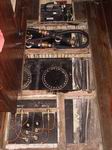
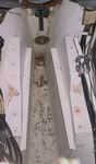
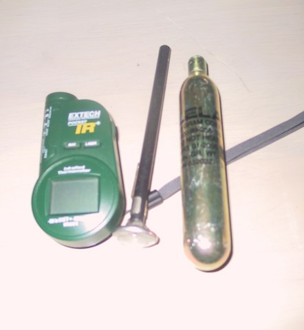
 TropiKool Summary - Now that the major kinks are worked out, we are very
happy with the system. We have a 1.1 ft3 freezer maintaining
25oF and a 3.8 ft3 refrigerator at 50oF.
After a 2-day stabilization period in 75oF ambient air our unit
draws a continuous 2.2 amps @ 12.10 VDC, about 53 amp hours per day. As
reference, this is slightly less than our old Adler Barbour Cold Machine
which had half the freezer space but little refrigerator insulation. Once
stabilized, compressor noise subsides quite a bit but we will be trying some
sound baffling techniques to try to reduce it still more. One of the real
benefits of this system is simplicity of maintenance. The picture on the
right shows the special tools we use to maintain the TropiKool refrigeration
system - thermometers and CO2 cartridges!
TropiKool Summary - Now that the major kinks are worked out, we are very
happy with the system. We have a 1.1 ft3 freezer maintaining
25oF and a 3.8 ft3 refrigerator at 50oF.
After a 2-day stabilization period in 75oF ambient air our unit
draws a continuous 2.2 amps @ 12.10 VDC, about 53 amp hours per day. As
reference, this is slightly less than our old Adler Barbour Cold Machine
which had half the freezer space but little refrigerator insulation. Once
stabilized, compressor noise subsides quite a bit but we will be trying some
sound baffling techniques to try to reduce it still more. One of the real
benefits of this system is simplicity of maintenance. The picture on the
right shows the special tools we use to maintain the TropiKool refrigeration
system - thermometers and CO2 cartridges!
Other refit pictures

 Boat refits tend to be ongoing and Horizon's refit will be no
exception. The haulout phase of this refit really got going in February 2003
when we realized there was enough money saved to put the new engine into
Horizon. We had purchased the Yanmar at the Miami boat show in 2002
but for 9 months it sat in our shed at the marina while we saved more money.
Like most things nautical, my original estimate to haul and install the
engine was far too low, but then we had lots of unexpected surprises. In the
end, our "2 week haul" turned into 10 weeks and the cost ballooned to 3 times
our worst-case estimate, but we think the results are worth it.
Boat refits tend to be ongoing and Horizon's refit will be no
exception. The haulout phase of this refit really got going in February 2003
when we realized there was enough money saved to put the new engine into
Horizon. We had purchased the Yanmar at the Miami boat show in 2002
but for 9 months it sat in our shed at the marina while we saved more money.
Like most things nautical, my original estimate to haul and install the
engine was far too low, but then we had lots of unexpected surprises. In the
end, our "2 week haul" turned into 10 weeks and the cost ballooned to 3 times
our worst-case estimate, but we think the results are worth it. 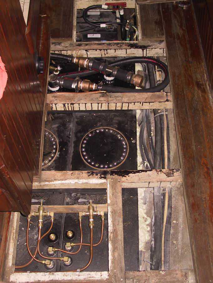


